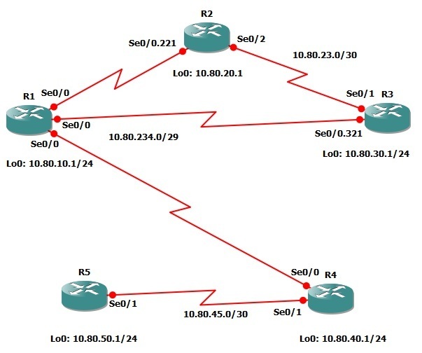
In this lab you will learn how to configure Enhanced Interior Gateway Routing Protocol (EIGRP) to advertise a default route throughout the routed domain using an aggregate address.
Real World Application & Core Knowledge
If you’ve completed all the previous labs found in Section 8, then you have knowledgeable understanding of how to configure the Enhanced Interior Gateway Routing Protocol (EIGRP) however there is one more topic left to touch upon before moving onto OSPF which is the ability to advertise a default route using EIGRP.
If you’ve completed Lab 7-7 – Configuring RIP Default Information Originate then you’ll have a good understanding of the benefits and operational concept of dynamically advertising a default route within the routed domain however; unlike RIP, EIGRP uses a two different methods commonly used to inject a default route into the EIGRP Topology table.
The first method being to advertising a 0.0.0.0/0 summary route via an interface to neighboring routers which will flag the route as the default and install it into the routing table as the gateway of last resort and the second way being to create a static route and redistribute that static route into the EIGRP autonomous system. This method will be discussed in Section 10.
In this lab you will learn to configure EIGRP to propagate the default route using a summary address on R1′s hub-and-spoke frame-relay interface. (Serial1/0). When configuring a default summary route for EIGRP, the router advertising the EIGRP default summary route will suppress any upstream routes learned and only send the default summary route to down stream neighbors. For an example; vision three routers connected via serial links in a a linear bus topology. R1 is connected to R2, then R2 is connected to R3. If you configure a default summary route on the two interfaces of R2 facing R1 and R3, when R3 advertises directly connected networks to R2, R2 will install those networks in its own routing table and only advertise a default route to R1.
However if a single edge router connecting to the internet is advertising a default route via a summary-address into EIGRP network then the default router will not be in the transit path of internal traffic thus all internal routers will have the full internal routing table.
You will use the same command as discussed in the previous lab; ip summary-address eigrp as# n.n.n.n s.s.s.s to advertise a default route from R1 to the spoke routers in the hub-and-spoke topology which include R1, R2, R3 and R4.
This lab will continue to build upon the topology previously used in Lab 8-8 and other labs found through out Section 8.
Lab Prerequisites
• If you just completed Lab 8-8 you may start where you left off, if not you can load the Free CCNA Workbook GNS3 topology; start and establish a console session with R1, R2, R3, R4 and R5 then load their initial configurations included below by copying the config from the textbox and pasting it into the routers console.
Initial Configurations
Lab Objectives
• Create a summary route to advertise the address of the 0.0.0.0/0 network on R1′s hub-and-spoke serial interface.
• Examine the routing tables on R3 and R4 to ensure the default route is being learned from R1 as well as other routes.
Lab Instruction
Objective 1. – Create a summary route to advertise the address of the 0.0.0.0/0 network on R1′s hub-and-spoke serial interface.
R1>enable |
Objective 2. – Examine the routing tables on R3 and R4 to ensure the default route is being learned from R1 as well as other routes.
R3#show ip route |
If you examine the routing table of R3 as shown above you’ll notice that the default route 0.0.0.0/0 is being learned via 10.1.234.1 on interface Serial1/0.321 however you’ll also notice that routes that are advertised by R4 and R5 are no longer in the routing table as but you can still ping those destinations. This is due to R1 only advertising the default route to neighboring routers.
In this case, R4 advertises all its connected networks such as 10.55.40.0/24 to R1 then R1 places this route in its routing table but only advertises a default route to R2 and R3 however R2 and R3 are still able to get to R4′s networks using only the default route.
You can see from examining the routing table of R4 shown below that the same thing is occurring to R4 as it only has a default route which points to R1 and the previous more specific routes pointing towards R1 orginally advertised by R2 and R3 have disappeared.
R4#show ip route |
If you view the EIGRP topology table on R4 you’ll notice that routes from R3 are not being advertised to R4 via R1 but instead only a default route is advertised as shown below;
R4#show ip eigrp topology |
As shown above in R4′s EIGRP topology routes to 10.55.20.0/24, 10.55.30.0/24 and 10.1.23.0/30 do not exist however a route to 0.0.0.0/0 does which points to R1 which in turn has the missing routes from R4′s routing table thus the giving full ip reachability as shown below with the ping command;
R4#ping 10.55.30.1 source lo0 |
The more preferred way of injecting a default route into the EIGRP topology is by redistributing a static route into EIGRP which will show up as an External EIGRP Route in the routing table as denoted by “D*EX” next to the route and having an administrative distance of 170. This method will be discussed in Section 10 – Redistribution.

0 komentar:
Posting Komentar
Silahkan isi kesan hati anda di sini !!!