Real World Application & Core Knowledge
In lab 9-1, the process of the Router-ID determination was discussed and through out Section 9 labs when you’ve used the show ip ospf neighbor command and I’m sure you’ve noticed the neighbor id and that it was the IP Address of the neighbors loopback0 interface. As discussed in Lab 9-1, there is a reason for this. The Router-ID uniquely identifies a router in an autonomous system, no two routers in an OSPF autonomous system can have the same router-id.If a router-id is not configured manually in the OSPF routing process the router will automatically configure a router-id determined from the highest IP address of a logical interface (loopback interface) or the highest IP address of an active interface. When referring to a higher IP address, step back and look at the IP address as a whole number. For example, 1.1.1.1 translates to 1,111 and 2.2.2.2 translates to 2,222; in which case 2,222 is a higher number than 1,111.
The router id is used in several OSPF related commands such as the specifying a specific neighbor when clearing a neighbor relationship or when viewing neighbor parameters by using the show ip ospf neighbor rid.
When configuring a router-id, the neighbors will not be updated automatically until that router has failed or the OSPF process has been cleared and the neighbor relationship has been re-established.
In this lab you will statically configure the Router-ID’s on all routers in the topology using the router number as the router-id. i.e; R1′s router-id would be 1.1.1.1
Familiarize yourself with the following new command(s);
router-id x.x.x.x – This command is executed in OSPF router configuration mode to statically configure a router id on a specific neighbor.
show ip ospf proc-id – This command is executed in privileged mode to view OSPF process parameters such s the local router-id and OSPF area information related to that router.
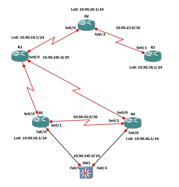
The following logical topology shown below is used in labs found through out Section 9 – Configuring OSPF;
Lab Prerequisites
• If you completed lab 9-5 you can start where you’ve left off or you can load the Free CCNA Workbook GNS3 topology; start and establish a console session with R1, R2, R3, R4, R5 and SW1 then load their initial configurations included below by copying the config from the textbox and pasting it into the routers console.
Initial Configurations
Lab Objectives
• Configure each router with a router-id that reflects the router number. i.e; R1′s Router-id would be 1.1.1.1
• Clear the OSPF process on each router and verify on R1 that the new router ID’s are be used by viewing R1′s OSPF neighbors.
Lab Instruction
Objective 1. – Configure each router with a router-id that reflects the router number. i.e; R1′s Router-id would be 1.1.1.1
R1#configure terminal |
R2#configure terminal |
R3#configure terminal |
R4#configure terminal |
R5#configure terminal |
Objective 2. – Clear the OSPF process on each router and verify on R1 that the new router ID’s are be used by viewing R1′s OSPF neighbors.
R1#clear ip ospf 1 proc |
R2#clear ip ospf 1 proc |
R3#clear ip ospf 1 proc |
R4#clear ip ospf 1 proc |
R5#clear ip ospf 1 proc |
Once you’ve cleared the OSPF process as shown above on R1 through R5 the neighbor relationships will drop and reform, once all neighbor relationships have been re-established you can then view the ospf neighbor table on R1 to verify that the router-id’s have indeed been changed;
R1#show ip ospf database |
To verify that R3′s router ID has been changed you can view the neighbor relationships on R2 as shown below;
R2#show ip ospf database

Neighbor ID     Pri   State           Dead Time   Address         Interface
1.1.1.1           1   FULL/DR         00:01:50    10.1.245.1      Serial1/0
3.3.3.3           0   FULL/  -        00:00:36    10.1.23.2       Serial1/2
R2#

0 komentar:
Posting Komentar
Silahkan isi kesan hati anda di sini !!!