In this lab you will learn how to configure an Open Shortest Path First (OSPF) passive interface to prevent OSPF from forming neighbor relationships on an OSPF enabled interface.
Real World Application & Core Knowledge
If you’ve completed Lab 8-7 – Configuring EIGRP Passive Interface then you should have a firm understanding of how passive interface works and what it does.
If not then to summarize passive-interface up in one paragraph; its a feature you enable on a per interface basis which allows a particular interface to participate in a routing process but prevents that interface from forming neighbor relationships by not sending hello packets and discarding received hello packets.
So you’re probably wondering what is this feature good for? Lets say you have a layer 2 access switch and all layer 3 functions of the network occur at the distribution layer. In this case you would not want the router(s) sending hello packets down to the access switch but you’d still want the links participating in a routing protocol to be advertised dynamically. In this case you’d need to use the passive interface feature.
You configure a passive interface in OSPF the same way you do in EIGRP and RIP by using the passive-interface interfacename#/# in router configuration mode.
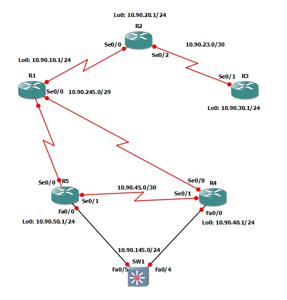
In this lab you’ll be configuring the LAN interfaces on R4 and R5 as passive interfaces to ensure they do not form a neighbor relationship with each other however they must advertise the LAN network 10.45.1.0/24 into the OSPF autonomous system.
Familiarize yourself with the following new command(s);
passive-interface interfacename#/# – This command is executed in router configuration mode to specify a particular interface as a passive-interface in the dynamic routing process. A passive interface does not send or process received hello’s thus not forming a neighbor relationship or advertising routes.
The following logical topology shown below is used in labs found through out Section 9 – Configuring OSPF;
Lab Prerequisites
• If you completed lab 9-11 you can start where you’ve left off or you can load the Free CCNA Workbook GNS3 topology; start and establish a console session with R1, R2, R3, R4, R5 and SW1 then load their initial configurations included below by copying the config from the textbox and pasting it into the routers console.
Initial Configurations
Lab Objectives
• Configure R4 and R5′s LAN interfaces (FastEthernet0/0) as passive interfaces to ensure R4 and R5 never become neighbors over through the LAN.
• Verify on R1 that the routes to R4 and R5′s connected LAN is still in the routing table.
Lab Instruction
Objective 1. – Configure R4 and R5′s LAN interfaces (FastEthernet0/0) as passive interfaces to ensure R4 and R5 never become neighbors over through the LAN.
R4#configure terminal |
R5# |
Objective 2. – Verify on R1 that the routes to R4 and R5′s connected LAN is still in the routing table.
R1#show ip route |
As you can see from the routing table of R1 shown above that to get to the 10.45.1.0/24 network from R1 the next hop is R5. If you view the interface configuration on R5 you’ll see it has an ospf cost of 100 as previously configured in Lab 9-10 – Configuring OSPF Interface Cost before the auto-cost reference-bandwidth was changed in Lab 9-11 – Configuring OSPF Auto Cost Reference Bandwidth to ensure traffic coming from R1 would take R4 to get to 10.45.1.0/24 as R4 used the default cost reference which gave its FastEthernet0/0 interface a cost of 1 thus the ip ospf cost 100 on R5′s FastEthernet0/0 interface would be a higher. But after the auto cost reference bandwidth change R5 became the preferred route as OSPF dynamically calculated a higher cost then 100 for R4 to its FastEthernet0/0.
To resolve this you can change the cost on R5′s FastEthernet0/0 interface to 65535 as shown below;
R5#configure terminal |
View R1′s routing table as shown below; you’ll notice that the R1 now has the correct route to 10.45.1.0/24 through R4.
R1#show ip route
Codes: C - connected, S - static, R - RIP, M - mobile, B - BGP
      D - EIGRP, EX - EIGRP external, O - OSPF, IA - OSPF inter area
      N1 - OSPF NSSA external type 1, N2 - OSPF NSSA external type 2
      E1 - OSPF external type 1, E2 - OSPF external type 2
      i - IS-IS, su - IS-IS summary, L1 - IS-IS level-1, L2 - IS-IS level-2
      ia - IS-IS inter area, * - candidate default, U - per-user static route
      o - ODR, P - periodic downloaded static route

Gateway of last resort is not set

    10.0.0.0/8 is variably subnetted, 9 subnets, 4 masks
O IA    10.55.50.1/32 [110/64767] via 10.1.245.5, 00:55:05, Serial1/0
O IA    10.55.40.1/32 [110/64767] via 10.1.245.4, 00:55:05, Serial1/0
O IA    10.1.23.0/30 [110/129532] via 10.1.245.2, 00:54:55, Serial1/0
O IA    10.55.30.1/32 [110/129533] via 10.1.245.2, 00:45:11, Serial1/0
O IA    10.45.1.0/24 [110/65766] via 10.1.245.4, 00:01:05, Serial1/0
O IA    10.1.45.0/30 [110/129532] via 10.1.245.5, 00:54:55, Serial1/0
                    [110/129532] via 10.1.245.4, 00:54:55, Serial1/0
O IA    10.55.20.1/32 [110/64767] via 10.1.245.2, 00:55:05, Serial1/0
C       10.55.10.0/24 is directly connected, Loopback0
C       10.1.245.0/29 is directly connected, Serial1/0
R1#

0 komentar:
Posting Komentar
Silahkan isi kesan hati anda di sini !!!